4-Bar Linkage Project
- jasonpardliew
- Aug 20, 2017
- 3 min read

Our project involved studying the feasibility of drawing a pseudo ellipse shape by using a four-bar linkage. We were also concerned with the repeatability of the mechanism and how similar consecutive curves would be to each other. In order to create this mechanism, we took a three step approach. The first step involved iterating through different designs and deciding which criteria were the most important. Once a design was selected, the parts were manufactured using the laser cutter. The final step was to assemble the mechanism and test it on the testing setup.
The results of our testing were very promising. Not only did our mechanism draw the curve correctly on the first trial, but the process was very precise and repeatable. The marker traversed at a relatively constant speed and drew a very smooth, even curve. This implies that our initial design iterations were valuable. We were able to eliminate potential problems before we ran into them, saving both time and material. Looking forward, we could repeat the process in order to draw other shapes of create mechanisms that will serve other purposes. We have proven our ability to successfully design, manufacture, and assemble working mechanisms.
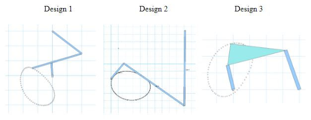
Before starting to generate design iterations, some of the product design specifications that we followed include: (i) the mechanism would be a four-bar mechanism in which a marker pen is attached to the coupler to draw a pseudo ellipse shape, (ii) the mechanism would be driven by a D-shaft that is attached to a motor, and (iii) the mechanism would not go outside an 18” x 12” wooden base. Under these guidelines, we came up with three different designs as follow:

The next step in our ideation process was to analyze each of the designs using the following Pugh chart:

For each of the designs, the pugh chart contains a more detailed analysis beyond the product design specifications. One of the more important considerations was a constant drawing speed to keep a consistent intensity for each part of the drawn line. A constant drawing speed would also prevent an acceleration surge that could create unwanted stresses on the links due to forces from the motor and the friction between the marker and the drawn surface. Based on the results from the pugh chart, we decided to pursue design 1.
Another important part in designing our mechanism was to make sure that the mechanism complied with the grashof condition. The grashof condition is simply an equation to show that if it is satisfied, the mechanism crank would be able to turn a full rotation without problem. If the length of the shortest and longest links were added up and shorter than the sum of the length of the other links, then the grashof condition is successfully fulfilled.

In the end, the use of pugh chart analysis was beneficial to our group because we found that Design 1 worked well according to our design specifications, even during preliminary prototyping stage. In total, we manufactured four links and saved the majority of the 12”x 12” acrylic sheet given to us. The four links include an iteration of the crank link with a smaller D-hole dimension so that the shaft could be better press fitted into the ductile acrylic link. The consistency of intensity and placement of the pseudo ellipse curves also showed good drawing repeatability.
A PVA analysis was performed on the point where the marker was mounted on the coupler. The position of the marker is shown in the figure below, by the dotted outline. The x and y coordinates of the point are also shown in the first plot. The second plot shows the velocity of the marker. The velocity is held between a relatively small range, which was ideal for curve drawing. The third plot shows the acceleration of the marker. Again, the acceleration is relatively small and falls within a small range

Below are some CAD and engineering drawings that was produced to supplement this project.


Comments