Finite Element Analysis of Trusses
- jasonpardliew
- Aug 20, 2017
- 2 min read

In most scenarios, our knowledge of variables and technical requirements is incomplete, there are some information that we must assume to be true and some details that we neglect. In the field it is the engineer’s duty to make the project work on time, within budget, and without costly prototypes and testing. In this project, a model of a lego excavator is analyzed and inspected to estimate the strength of the lego pieces that make up the excavator lifting mechanism. Given known experimental data of previously tested parts and knowing that the material of the lego is ABS, the Young’s Modulus and Von Mises stresses to yield ABS plastic in compression and tension can be figured out by replicating the tests. Using this information the lego pieces can be simulated in Creo Parametric 3.0 and the force to break the lego part can be discovered by matching the Von Mises stress of the part at the failure point to the yielding Von Mises stress of the ABS plastic.
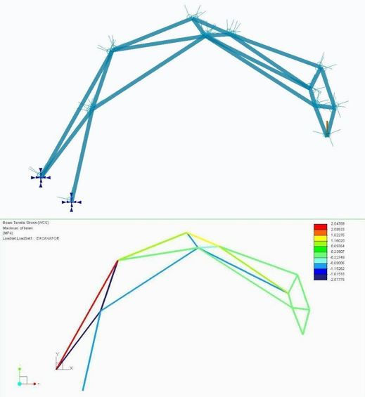
A simple 2D truss model of a lego excavator arm can be created in Creo Parametric to obtain all the joint forces as a preliminary guess. The 2D model can be constructed by knowing the location of the joints and connecting them by beams. A simple 2D statics analysis of the excavator arm can be used to calculate the joint forces for at least points 1,2,3,4,5, and 6. A sample calculation from the 2D analysis is shown below for your perusal.

Firstly, in order to start predicting load, we must find the characteristics of the material since it is not known. Data from previous tests are given as follows for compression and tension:
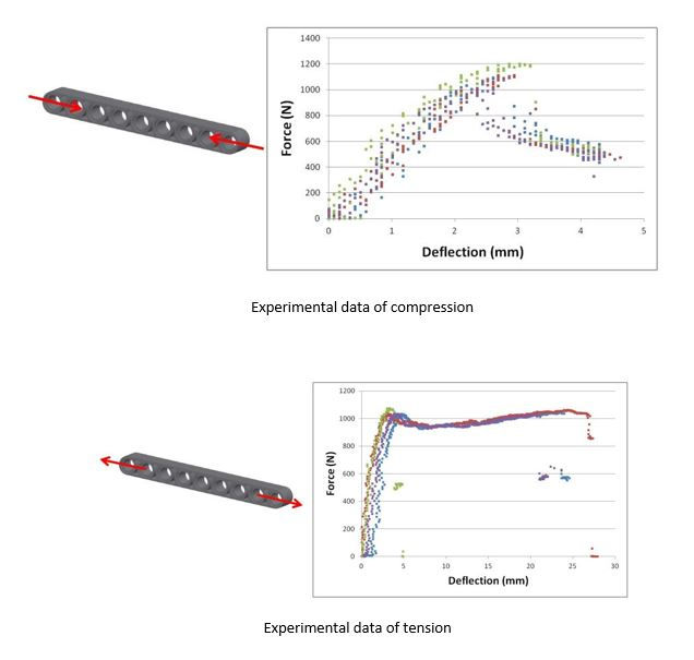
Using the experimental data given, we can find the Elastic Modulus by choosing an arbitrary point in the elastic region of the material. The value that was chosen to determine the Elastic Modulus was 800N which corresponds to a deflection of roughly 2.5mm. The part is then replicated in Creo Parametric 3.0 to follow the experimental data. The same procedure is conducted for compression using the compression experimental data.

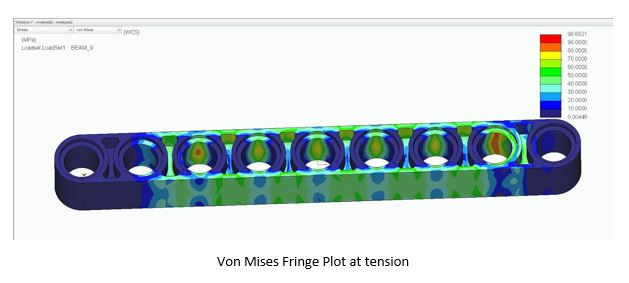
After running the analysis, the Von Mises Fringe plot can be seen in MPa. This Von Mises stress is the critical stress at which any Lego part in tension will fail. A similar procedure is used to find the critical Von Mises stress under compression loading. For other parts, the loading force shall be adjusted in order to match up the critical Von Mises stress. A simple relation can be used so that the analysis does not have to be run multiple times: F1 = F2 σ1 = σ2
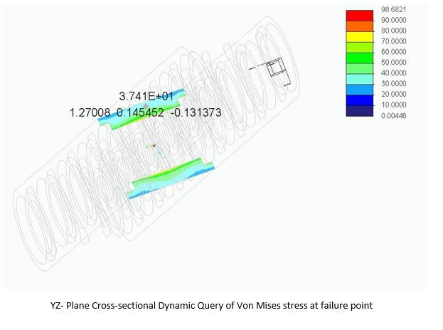
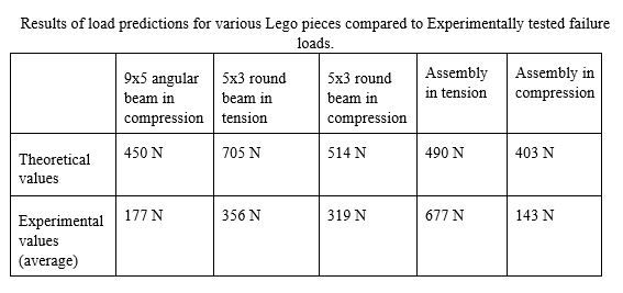
Using the series of methods described previously, the different parts of the lego excavator can be simulated and compared to experimental failure of the same part. These parts are shown below.
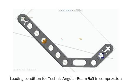
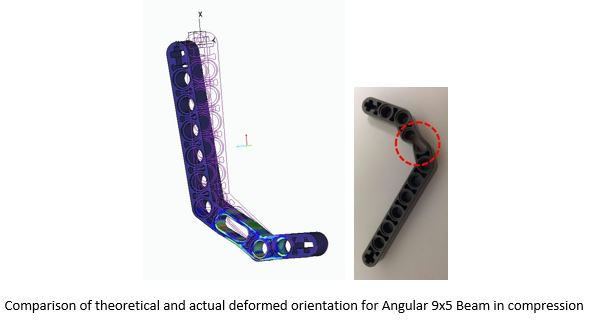
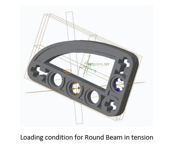
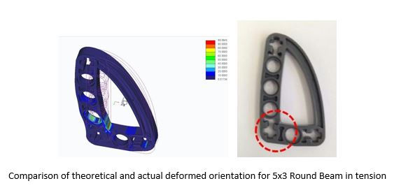
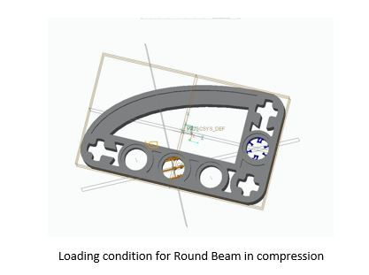


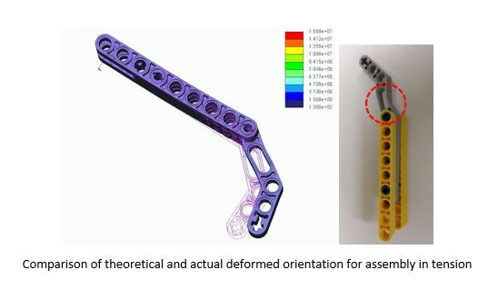
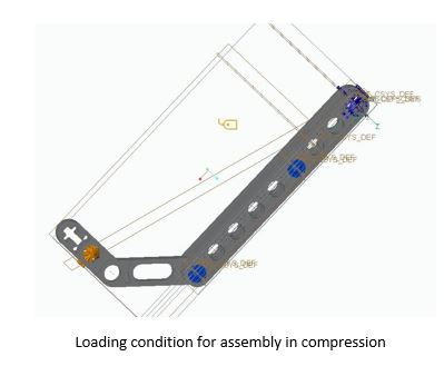
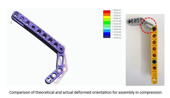
The final predicted results for the different lego pieces that make up the excavator is thus tabulated below.


Comments